
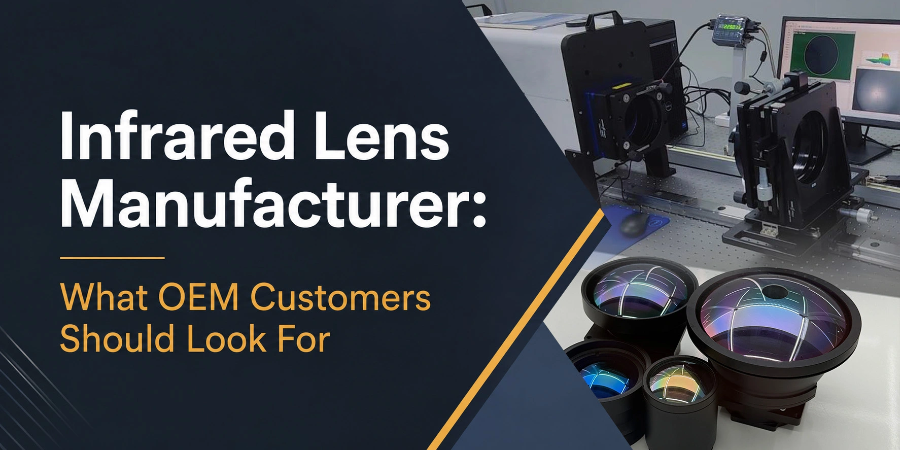
The Infrared Lens Manufacturing Process includes optical design, material preparation, lens fabrication, coating, housing machining, module assembly, inspection, packing and final delivery.
Manufacturers use this process to produce lenses and lens modules for LWIR and MWIR thermal imaging systems. These products support thermal cameras, surveillance systems, industrial inspection equipment, maritime monitoring, aerospace systems and defense applications.
Unlike standard visible lenses, infrared lenses must operate within specific infrared wavelength ranges. Therefore, manufacturers must select suitable optical materials, coatings, housing structures and assembly methods for the final camera system.
The complete manufacturing process normally includes two main areas:
- Optical lens manufacturing
- Mechanical housing or casing manufacturing
After producing these parts, the manufacturer assembles, aligns, tests and packs the complete infrared lens module.
Infrared Lens Manufacturing Process Overview
A typical infrared lens production process includes the following stages:
- Requirement review
- Optical and mechanical design
- Infrared material preparation
- Lens cutting and shaping
- Diamond turning, grinding or polishing
- Infrared coating
- Optical element inspection
- Housing and casing manufacturing
- Lens module assembly
- Alignment and adjustment
- Final optical and mechanical inspection
- Cleaning and packing
- Warehouse preparation and delivery
Each stage helps ensure that the completed lens module matches the optical, mechanical and functional requirements of the thermal imaging system.
1. Infrared Lens Requirement Review
The infrared lens manufacturing process starts with a review of the customer’s optical and mechanical requirements.
Important information normally includes:
- Wavelength range, such as LWIR or MWIR
- Detector resolution
- Detector pixel size
- Focal length
- F-number
- Field of view
- Lens type
- Focus requirement
- Housing or mounting interface
- Operating environment
- Required quantity
The lens type may include a fixed focus lens, athermalized lens, continuous zoom lens, dual field-of-view lens or motorized focus lens.
During this stage, the engineering team checks whether the requested design, material, coating and manufacturing method suit the application. As a result, the team can identify potential technical issues before production begins.
2. Optical and Mechanical Design
After reviewing the requirements, the engineering team prepares or checks the optical and mechanical designs.
Optical Design
The optical design determines how the lens collects infrared energy and focuses it onto the detector.
The designer considers:
- Image quality
- Focal length
- Wavelength range
- Detector size
- Pixel size
- F-number
- Field of view
- Distortion
- MTF performance
- Working distance
- Temperature range
The design must match the selected infrared detector. Otherwise, the lens may not provide the required field of view, image quality or resolution.
Mechanical Design
The mechanical design controls how the lens elements fit inside the housing.
It may include:
- Lens spacing
- Housing dimensions
- Mounting threads
- Retaining rings
- Focus movement
- Zoom movement
- Motor installation
- Cable position
- Camera interface
For an infrared lens module, the optical and mechanical designs must work together. Therefore, both teams must confirm lens spacing, movement range and mounting dimensions before manufacturing starts.
3. Infrared Lens Material Preparation
Next, the manufacturer prepares the selected infrared optical materials.
Common infrared lens materials include:
- Germanium
- Silicon
- Zinc Selenide, or ZnSe
- Zinc Sulfide, or ZnS
- Chalcogenide glass
- Other infrared optical materials
Material selection depends on the wavelength range, transmission requirement, operating temperature, mechanical environment and budget.
For example, Germanium commonly supports LWIR thermal imaging systems. Meanwhile, Silicon often supports selected MWIR applications. Chalcogenide glass can also provide an alternative for certain infrared lens designs.
The manufacturer cuts the raw material into suitable sizes before precision processing.
4. Lens Cutting and Shaping
The manufacturer then cuts or shapes the infrared material into lens blanks.
At this stage, the lens blank moves closer to the required:
- Diameter
- Center thickness
- Edge thickness
- Curvature
- General surface shape
This early shaping stage removes excess material and prepares the blank for precision machining.
Accurate blank preparation can also reduce processing time during diamond turning, grinding or polishing.
5. Diamond Turning, Grinding and Polishing
The next stage of the infrared lens fabrication process creates the required optical surfaces.
The manufacturer selects the production method according to the optical material, lens shape, drawing tolerance and final application.
Diamond Turning
Single-point diamond turning can create precise infrared optical surfaces. Manufacturers often use it for:
- Infrared lenses
- Aspheric lenses
- Complex surface profiles
- Prototypes
- Small or medium production quantities
The diamond tool removes material with high precision and produces the required optical surface profile.
Grinding
Grinding creates the basic lens curvature and removes material from the lens blank. It also prepares the surface for further polishing when the specification requires a polished optical finish.
Polishing
Polishing improves the optical surface quality and reduces surface roughness. The process may also help the lens meet surface quality, surface form and transmission requirements.
In simple terms:
- Diamond turning creates precise optical surfaces
- Grinding forms the required lens shape
- Polishing improves the optical finish
Some lens designs may use one process, while others may require a combination of these methods.
6. Infrared Lens Coating
After lens fabrication, the manufacturer applies the required infrared coating.
Uncoated infrared materials can lose a significant amount of light through surface reflection. Therefore, an optical coating helps improve transmission and reduce unwanted reflection.
Common coating options include:
- Anti-reflection coating
- Broadband anti-reflection coating
- Diamond-Like Carbon coating for selected external surfaces
- Custom infrared coating
The coating design must match the operating wavelength range. Common examples include:
- MWIR coating for 3–5 µm
- LWIR coating for 8–12 µm
- Custom broadband infrared coating
DLC coating can also improve surface durability for selected exposed optical surfaces. However, the exact coating choice depends on the lens material, environment and transmission requirement.
7. Infrared Lens Inspection
After fabrication and coating, the quality team inspects each optical element.
Inspection may include:
- Diameter
- Center thickness
- Edge thickness
- Surface quality
- Surface profile
- Radius
- Centering
- Clear aperture
- Coating appearance
- Coating adhesion
- Spectral transmission
- Other drawing requirements
The quality team compares the inspection results with the approved drawing and specification.
Consequently, only suitable lens elements move to the assembly stage.
8. Infrared Lens Housing Manufacturing
While the optical team produces the lenses, the mechanical team can manufacture the lens housing or casing.
The housing holds the optical elements at the correct position and spacing. In addition, it connects the lens module to the camera system.
Housing production may include:
- CNC machining
- Turning
- Thread machining
- Mounting interface machining
- Internal structure machining
- Surface treatment
- Blackening
- Anodizing
- Mechanical dimension inspection
A well-designed housing supports stable alignment and protects the lens elements. It may also control manual focus, motorized focus or zoom movement.
For zoom lens modules, the housing requires additional moving structures, guide mechanisms and motor interfaces.
9. Infrared Lens Module Assembly
Once the optical elements and housing parts pass inspection, the assembly team builds the infrared lens module.
The team installs each lens element according to the approved optical and mechanical design.
The assembly may include:
- Infrared lens elements
- Spacers
- Retaining rings
- Sealing parts
- Focus mechanism
- Zoom mechanism
- Motors
- Control board or controller
- Cables
- Mechanical interface components
The team must carefully control the orientation, spacing and position of every lens element. Even a small positioning error can affect focus, centering and final image performance.
Therefore, the assembly process follows controlled instructions and inspection procedures.
10. Alignment and Adjustment
After assembly, the engineering team aligns and adjusts the lens module.
The alignment process helps confirm:
- Optical axis position
- Focus position
- Lens centering
- Detector matching
- Image quality
- Zoom tracking
- Mechanical movement
For fixed focus lenses, the team sets and verifies the required focus position.
For motorized focus or zoom lenses, the team also tests the motors, cables, control response and movement range. In addition, the team may check whether the lens maintains focus throughout the zoom range.
11. Final Infrared Lens Module Inspection
Before delivery, the completed infrared lens module goes through final optical, mechanical and functional inspection.
Common inspection items include:
- Appearance
- Mechanical dimensions
- Focus position
- Image quality
- MTF performance, when required
- Field of view
- Distortion
- Zoom operation
- Motorized focus operation
- Coating and optical surface condition
- Mounting interface
- Cable and connector function
- Control response
- Environmental performance, when required
The quality team may connect the lens to a compatible detector or thermal camera core for image testing.
This final inspection confirms that the finished module meets the agreed specification before packing.
12. Cleaning and Packing
After final inspection, the production team cleans the lens module.
Proper cleaning removes:
- Dust
- Particles
- Fingerprints
- Oil
- Assembly residue
The team must protect infrared coatings and optical surfaces throughout the cleaning process.
After cleaning, the team packs the product with suitable protective materials. Depending on the product, the packaging may include:
- Lens caps
- Protective film
- Individual plastic bags
- Foam inserts
- Plastic cases
- Inner cartons
- Export cartons
- Product labels
- Inspection documents
Good packaging protects the infrared lens module during storage, handling and transportation.
13. Warehouse and Final Delivery
After packing, the team moves the finished infrared lens modules to the warehouse or shipment area.
The delivery documents may include:
- Commercial invoice
- Packing list
- Inspection report
- Material certificate
- Coating report
- Product label
- User instructions
- Control protocol
- Other customer-requested documents
Finally, the logistics team checks the quantity, packaging, shipping address and delivery method before dispatching the goods to the customer.
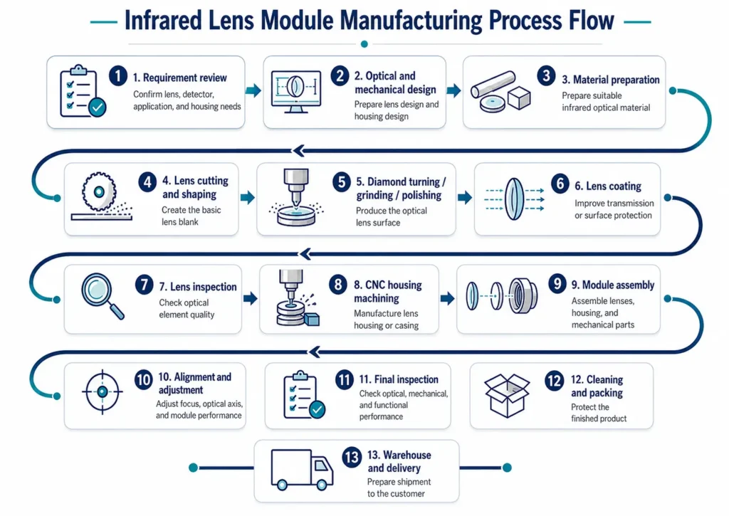
Simple Process Flow
Information Required for Infrared Lens Manufacturing
To support an infrared lens or lens module project, customers should provide as much technical information as possible.
Useful information includes:
- Lens type: fixed focus, athermalized, zoom or dual FOV
- Wavelength range: LWIR or MWIR
- Detector type
- Detector resolution
- Pixel size
- Focal length
- F-number
- Field of view
- Focus type: fixed, manual or motorized
- Zoom range, when applicable
- Housing or mounting interface
- Operating temperature
- Environmental requirements
- Quantity
- Optical drawing
- Mechanical drawing
- 3D model or interface file
Clear information helps the lens manufacturer recommend a suitable optical design, material, coating, housing structure and production method.
Example Infrared Lens Module Specification
| Item | Example Specification |
|---|---|
| Lens Type | LWIR continuous zoom lens module |
| Wavelength Range | 8–12 µm |
| Detector Type | Uncooled LWIR detector |
| Detector Resolution | 640 × 512 |
| Pixel Size | 12 µm |
| Focal Length | 20–120 mm |
| F-number | F/1.1 |
| Focus Type | Motorized focus |
| Zoom Control | Motorized zoom |
| Coating Requirement | AR coating for 8–12 µm |
| Application | Thermal imaging, surveillance, long-range observation |
| Interface / Mount | Customizable based on camera system |
| Quantity | 1 set / prototype / batch production |
Conclusion
The Infrared Lens manufacturing process combines optical fabrication, precision mechanical machining and controlled module assembly.
First, the engineering team reviews the application and prepares the optical and mechanical designs. Next, the production team cuts, shapes, machines, polishes and coats the infrared lens elements.
At the same time, the mechanical team uses CNC machining to produce the lens housing and related components. The assembly team then installs the lenses, spacers, retaining rings, motors and other parts into the housing.
Finally, the quality team aligns, tests and inspects the complete lens module. After cleaning and packing, the logistics team prepares the finished product for warehouse storage and final delivery.
Shape Optics provides LWIR and MWIR infrared lenses, including fixed focus lenses, athermalized lenses, continuous zoom lenses, dual field-of-view lenses, motorized focus lenses and custom infrared lens modules.
Contact Shape Optics to discuss your infrared lens or infrared lens module requirements.